ATLAS Thin Gap Chamber
Cable connection between ASD and PS-Pack
B.J. Ye(a) , T.Takeshita(b), K.Hasuko(a), T. K.Ohska(c)
O.Sasaki(d), T.Kobayashi(a)
(a)ICEPP, University of Tokyo, Japan
(b)Physics Department, Shinshu University, Japan
(c)International Collaboration Office, KEK, Japan
(d)Institute of Particle and Nuclear Studies, KEK,Japan
Contact person:
Bangjiao Ye, bjye@online.kek.jp and Tohru Takeshita, tohru@shinshu-u.ac.jp
This document is avarable in a pdf file (400kb) , as well.
1. Introduction
This is a draft design of the connection between Amplifier-Shaper-Discriminator
(ASD) Boards, Patch-Panel (PP) and Slave Boards (SLB) for the
front-end electronics of the Thin Gap Chamber (TGC) trigger system.
We will discuss cable route, mount, its length and weight as well
as time delay.
The ATLAS experiment in the LHC uses TGC as its forward muon trigger
detector. The TGCs are mounted in six big wheels, M1, M2 and M3
in each side(A and C) which support mechanically. M1 has three
TGC layers, called as triplet. M2 and M3 both have two TGC layers
called as doublet. The inner wheel is a doublet of TGC. The total
number of TGCs is about 3600. The total number of TGC signals
for wires and strips is nearly 321k channels.
A PS-Pack serves 1/24th of triplet (M1) or two doublets (M2 and
M3). A sub-PS-Pack consists of 1 mother Patch-Panel (PP) board,
2 daughter PP boards and 2 Slave Boards (SLB), which is called
a standard sub-PS-Pack unit. A sub-PS-Pack unit is shown in Fig.1
schematicaly. The signals from the Amplifier-Shaper-Discriminator
(ASD) Board are sent though a 20-pair twisted-pair cable to the
PS-Pack. Each ASD Board consists of 4 ASD chips which corresponds
to 16 wires/strips channels. Each unit of sub PS-Pack serves 16
ASD Boards which equals to 256 channels in the maximum (one exception
exists in doublet which serves 18 ASD Boards corresponding to
258 channels) for doublet.
The wheels M1, M2 and M3 are divided into 24 identical elements, called sets. Three sets make an octant. Each set is divided radially into two regions, named Forward and End-cap.
The ASD Board is physically attached to the edge of a TGC and
enclosed inside the TGC electrical shielding (Faraday cadge).
Signals from the ASD Boards are sent to a Patch-Panel (PP) board,
which houses receivers for the ASD outputs, TTC receivers and
DCS, Bunch-Crossing Identification circuits, logic to take care
of physical overlap in the TGCs and fan-outs. Outputs from the
PP board are sent to corresponding Slave Board (SLB) where the
coincidence and read-out circuits are placed. For M1 wheel, three
groups of two ASD Boards are served by a SLB, which allows a 2-out-of-3
coincidence to be formed. For M2/M3 wheels, four groups of two
ASD Boards are served by each SLB and a 3-out-of-4 coincidence
is made.
The PS-Pack, which consists of PP and SLB, are placed on the accessible
surfaces of the TGC wheels. Thus, PS-Pack for the M2 and M3 are
mounted on the outer surface of the M3 wheel and those for the
M1 are mounted on the inner surface of the M1 wheel.
The powers of PS-Packs are about 185W/set for doublet and 80W/set
for triplet. Total power of PS-Pack is 13kW which will most transfer
into heat. A cooling system is needed for removing heat. The double
U-shape coolant pipe system has designed for cooling the PS-Pack.
The cooling pipes made of Al is used not only as cooping pipes
and but also as support bars for the PS-Pack. Low voltage is supplied
by LV bus which consists of 4 wires (3.3V, ±3V and common ground)
as shown in Fig.2.
The total number of electronic channels in the TGC system is 321k.
The details of the channel distribution over the four sub-wheels
are given in Table 1. Table 2 gives the total number of channels,
ASD Boards and SLBs for a set (1/24), octant, one side and both
sides.
There are 35 SLBs per set for the doublet, 23 SLBs for the triplet
and 2 SLBs for the inner wheel. In order to reduce physical size
of a PS-Pack, a high-density connector (KEL, 8830E-080-170L) is
used at the PP board. With this connector, the length of a sub-PS-Pack
can be designed to be 510 mm. Because the avairable radial length
on the outer surface of M3 wheel is only 6000 mm, we arrange the
PS-Pack in two layers construction. It occupies 5000 mm in length
including Service PP board. We arrange all sub-PS-Packs in one-line
configuration so that other service systems such as LV supply
and cooling system can be simply in construction.
For the PS-Pack of triplet, it is a bit more complex than that
of doublets because the support bar of TGC limits the avairable
length on the inner surface of M1 wheel. The total usable radial
length is 2500 mm, however, we need 3200 mm to arrange all sub-PS-Packs
for M1 in one-line. We still designed all sub-PS-Pack units in
one line which is based on the assumption that the support bar
can be moved to the center of two TGCs by about 100 mm which can
increase the available length to 3200 mm.
Table 1 The number of Channels, ASD chip, ASD Board, PP and SLB
* For Inner wheel, each TGC has a slave board, that is, it combines wires and strips in one SLB.
Table 2 The number of channels, ASD Board and SLB
2 Connection between ASD and PS-Pack
2.1 ASD connector name
As have given above, each PS-Pack set which is a 1/24 of a wheel,
contains 141 ASD boards for triplet and 276 ASD boards for doublet.
For triplet, middle layer (TGC1) has 35 connectors and two sides
(TGC0 and TGC2) both have 53 connectors because there is not strip
output in the middle layer. For doublet, there are 70 connectors
per layer for M2 and 68 connectors per layer for M3. In order
to make a distinction for different ASD boards, we name each connector
of ASD boards as shown in Table 3.
TGCs were installed on both sides of ATLAS with a mirror structure
as shown in Fig.3. We use ŇAÓ to present the TGCs which located
in positive Z region and ŇCÓ present the TGCs located in negative
Z region. We use M1, M2 and M3 to present the three wheels. M1
is a triplet consisting of A, B and C layers. M2 and M3 are doublet
consisting of A and B layers. Each name of ASD connector for 1/24
wheel is shown in Fig.4 and Fig.5 for triplet and doublet, respectively.
Fig.3 TGC location and wheels
Table 3 ASD connector naming
Figure 4, ASD positions for Triplet.
Figure 5, ASD positions for Doublet.
2.2 Sub-PS-Pack names and arrangement
Patch Panels and Slave Boards are assembled into PS-Pack. There
are two kinds of PS-Pack: one is for the triplet (mounted on the
surface of M1 wheel) and another is for the doublet( M2 and M3,
mounted on the surface of M3 wheel). All sub-PS-Packs for 1/24
unit were arranged as two layers (upper and bottom layers). In
order to predigest the support scheme and cooling system, all
sub-PS-Packs are arranged in one-line structure. Total length
of a PS-Pack is 3.2m for triplet and is 5.0m for doublet, respectively.
Total numbers of PS-Packs are 24,24 and 8 for triplet, doublet
and inner wheel. Their names are given in Table 4.
Table 4 PS-Pack naming
Table 5 Patch Panel naming
Table 6 Slave Boards naming
Triplet example
Fig.6 Sub-PS-Pack location name for PP and SLB for Triplet
Doublet example
Fig. 7 Sub-PS-Pack location name for PP and SLB for Doublet
2.3 PP Connectors names
As mentioned before, each PP has two layers: one mother PP
and two daughter PPs. Each mother PP has 4 high density connectors
( one exception exists in doublet mother PP with 5 connectors)
and each daughter has 2 high density connectors. In order to distinguish
each connector in the same PP board, we give names to the connectors
as shown in Fig.8.
Fig.8 PP connectorŐs names
The connector named to be E0WD0-MA, for example, is the first connector (R is larger than others connectors in same PP) on the mother PP for the Patch Panel E0WD0 and also E0WD0-DC is the third connector on the daughter PP for the same PP. Since each PP connector connects to 2 ASD-board connectors, we have to distinguish the different part of in one connector. Upper part (R is larger, the green part in Fig.8) can be signed as 1 and bottom part as 2. Therefore, connector DA1 means the upper part of connector DA.
2.4 Connection between ASD boards and PP
The 16-ch ASD Board has designed and built for both wire signals
and strip signals from TGCs. Each board contains 4 ASD ICs with
protection circuits. The ASD borad is directory attached to the
TGC chamber. The ASD Board design is common for all TGC chambers.
16 LVDS logic signal outputs from the ASD Board are transmitted
through a 20-pair twisted-pair cable from an ASD board. An amplified
analog output through a LEMO type connector is equiped for each
ASD. DC power, ground, threshold voltage and test pulse are supplied
to the ASD Board by the same twisted-pair cable.
Each PP board consists of one mother PP and two daughters PPs
(in some case one PP board consists of one mother PP and one daughter
PP in order to save space). High density connectors are used as
the connectors which receive signal from ASD Board in both mother
and daughter PP. Each PP connector responds to two ASD boards
by the twisted-pair cable. The connection between ASD Board and
PP Board has two kinds of scheme: one is common connection and
another is special connection scheme which is a exception of common
connection. Fig.9 and Fig.11 are the common connection scheme
for doublet and triplet, respectively. Fig.10 and Fig. 12 are
two special connection for doublet and triplet, respectively.
All ASD connector connected to PP connector is one by one as shown
in Tables 8-11 for doublet and triplet.
Fig.9 Normal connection between TGC connectors and PP connectors
for doublet
Fig.10 An exception for the doublet PP board with three connectors
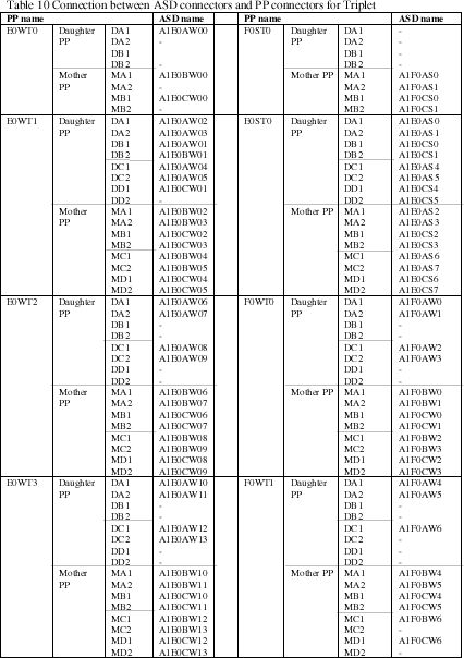
Fig.11 Normal connection between the ASD connectors and PP connectors for the triplet
Fig.12 An exception for triplet PP board
Table 8 Connection between ASD connectors and PP connectors for Doublet Endcap wires
* There is no A3E0A(B)W06 connectors
Table 9 Connection between ASD and PP on doublet for Forward Strip/Wire and Endcap Strip
Table 10 Connection between ASD connectors and PP connectors for Triplet
2.4 Mount scheme and cable route
The TGC system consists of two sides, A and C, which are mirror images of each other. The ASD Boards in TGCŐs edges are also different location as shown in Fig.13. We have considered this difference in the design of PS-Pack in order to decrease the cable length. Two kinds of PS-Pack were designed to meet the requirement for A and C sides: normal PS-Pack and upside-down PS-Pack as shown in Fig.14. In this case, about 1 ton flat cable can be reduced.
Fig.13 The location of ASD boards in TGC edge for A and C sides,
looking at the TGC from the interaction.
Fig. 14 Two kinds of PS-Pack schemes for both A and C sides, looking at the TGC from the interaction.
PS-pack located in the surface of M1 and M3. Total length is
5m and 3.2m for doublet and triplet as shown in Fig.15. The cooling
pipe which has two parallel holes inside for coolant as shown
in Fig.16 is also used as support bar of the PS-Pack. Additional
4 bars for support PS-Pack on the surface of TGC are needed for
doublet and 3 bars for triplet. These additional bars are fixed
with TGC support frames.
Fig.15 The location of PS-Pack in the 1/24 set
Fig.16 Cross section of the cooling pipe made of Al.
Each PP connector receives wire and strip signals which come
from different ASD Board by flat cables. The connection relation
between PP connector and ASD board is shown in tables 8-10. The
length of each flat cable has been estimated according to both
locations of PP connector and ASD Board as shown in Appendix.
Fig.17 shows the cable route for 1/24 of M3 wheel and Fig18 shows
a cable connection between M2 and M3 wheels. The cables from M2
wheel are grouped in a few groups. Some cable support bars are
needed for fixing the cable as shown in Fig.18 between M2 and
M3
Each PP connector receives wire and strip signals which come from
different ASD Board by flat cables. The connection relation between
PP connector and ASD board is shown in tables 8-10. The length
of each flat cable has been estimated according to both locations
of PP connector and ASD Board as shown in Appendix. Fig.17 shows
the cable route for 1/24 of M3 wheel and Fig18 shows a cable connection
between M2 and M3 wheels. The cables from M2 wheel are grouped
in a few groups. Some cable support bars are needed for fixing
the cable as shown in Fig.18 between M2 and M3.
Fig.18 Cable route between M2 and M3
3. Cable length, weight and time delay
3.1 Cable length and weight
Cable weight is a very important factor for the design of the
big wheel. We suppose that it uses flat cable without shielding.
The weight of flat cable with 40-wires is 0.2kg per meter. According
to the positions of the ASD connector and the PP connector, we
can estimate each length of the cable and also the total length
though. Table11 shows the length of cables for one PS-Pack set,
one side and total. If we consider that about 10% additional cable
is required for installing in turning the corner. The total length
of flat cable is about 70 km and 14 tons. The length of the cable
for each ASD connector link to PP connector is given in Appendix.
Table 11 Length and weight of cable
3.2 Time delay
In ATLAS, TGC is chosen for the trigger chamber in the end-cap.
It covers the pseudo-rapidity rang 1<h<2.4. TGC has excellent
timing resolution providing safe bunch-cross identification, owing
to their narrow gap. The trigger system is based on a coincidence
between a hit in the last station(M3) and a corresponding hits
in the second (M2) or/and first station (M1). The low-pT trigger
formed by a 3 out of 4 coincidence in TGC2 and TGC3. For the high-pT
trigger an additional 2 out of 3 coincidence in the triplet of
TGC1 is required.
The arrival timing of a signal at the input of the PP consists
of three parts: time of flight (TOF) of particles from colliding
point to TGC, signal transfer time from hit point inside of TGC
to the edge of TGC along the wire or strip and the signal transfers
time in the cable from ASD board to PP. Time delay depends on
the position of the hit point, size of TGC and length of cable.
Two type of TGCs, doublet and triplet, are located at about 14
m from the interaction point in the beam direction (z). Nine kinds
of different TGCs are taken into account for the time calculation.
The length of cable from ASD to PP depends on the locations of
ASD Board and PP. The arrived time of signal in PP is then expressed
as:
T=TOF+L1/v1+L2/v2
where TOF=L0/v0 , L0 is the flight distance from the interaction
point to the TGC as shown in Fig.19 and v0 is particle velocity
which is nearly equal to the light velocity , L1 is wire/strip
length from the hit point inside of TGC to ASD Board, v1 is the
propagation velocity of wire signal (27cm/ns) or of strip signal
(15 cm/ns), L2 is the cable length from ASD Board to PP, v2 is
the signal transfer velocity along the cable. In the calculation,
a half length of wire/strip for each TGC was assumed. The results
are shown in Fig.20 for doublet and Fig.21 for triplet. The arrived
time of signal to PP are from 66 ns to 80 ns for doublet and from
65 ns to 82 ns for triplet. The relative delay are shown in Fig.22
for doublet and Fig.23 for triplet.
The timing setup in a PP is very important because the asynchronous
TGC signals are bunched by bunch-crossing identification (BCID).
The time delay will be adjusted by an adjustable delay with 25
ns in a step 780ps in PP. The cable delay time is also tested
by test pulses which generated in PPs, that is, the ASD Boards
accepting the test pulses soon return them back to the PPs.
Fig.19 Timing calculation scheme in the end-cap
Fig.20 Time delays for each connector for the doublet
Fig.21 Time delays for each connector for the triplet
Fig.22 Relative time delays for the doublet
Fig.23 Relative time delays for the triplet
Appendix Minimum length of cable and time delay for double